This article describes step by step, how the NOWA-Design editor works.
The NOWA-Design editor combines visual scene creation with some constrained logic and lua scripting for more advanced logic between game objects and its components.
Lua is used for sand boxing.
A NOWA-Design project is just a folder on the resource system with a collection of *.scene files.
Each project contains one global.scene and an init.lua file.
The global.scene is like a static variable, that acts for all scenes. This is useful if in several scenes specifig game objects (like the player) should be re-used. In this case, each game object does possess the attribute „Is Global“, if set to true, the game object will not be stored in each scene file, but just in the global scene. The when a scene is loaded, each time also the global scene is loaded.
The init.lua file can be used to specify some global data like register events for all lua scripts, that are contained in the project.
For example the project SpaceGame is composed of the following scene files:
- global.scene
- Intro.scene
- Options.scene
- Save.scene
- Load.scene
- Level1.scene
- Level2.scene
- Some *.lua files for the logic.
- Optional: Some image files for terra layer.
For lua coding the zero brane studio is adviced. It has a good intelli sense for lua. Each time the NOWA-Engine is compiled, in the ‚bin/Release‘ folder a ‚NOWA_Api.lua‘ file is created, which can be copied, to the ‚../ZeroBraneStudio/api/lua‘ folder. After that, open the studio and goto ‚edit‘->’preferences‘->’settings:user‘. Overwrite the existing content with this one:
--[[--

  Use this file to specify **User** preferences.

  Review [examples](+C:\Program Files (x86)\ZeroBraneStudio\cfg\user-sample.lua) or check [online documentation](http://studio.zerobrane.com/documentation.html) for details.

--]]--

api = {'NOWA_Api'}
interpreter = "NOWA_Api"
autoanalyzer = true
acandtip.fillups = ".("
acandtip.ignorecase = true
acandtip.strategy = 1
outline.showcompact = false
outline.showflat = false
staticanalyzer.infervalue = true
staticanalyzer.luacheck = true
acandtip.nodynwords = false
acandtip.startat = 4
editor.tabwidth = 4
styles = loadfile('cfg/tomorrow.lua')('Tomorrow')
styles.indicator.fncall.fg = {240,0,0}
-- to change the type of the indicator used for function calls
styles.indicator.fncall.st = wxstc.wxSTC_INDIC_HIDDEN
First, lets describe briefly the complete menu.
File
- New: Configuration panel in order to create a new project and scene and choose to be used functionality.
- Open: Opens an existing project and scene.
- Save: Saves the current scene.
- Save As: Saves the current scene under a different name.
- Settings: Shows the configuration panel (same the new menu entry).
- Create Component Plugin: Creates a C++ project, which is specialized in creating an own componet and add it automatically as plugin. Note: The NOWA-Design editor will be closed, because the component must be compiled.
- Open Log: Opens the log file in a text editor.
- Copy Scene: Copies and stores the current scene under a different name. Note: Each lua script component, which is not a global script or common script will also be stored under a different name. So its possible e.g. to edit a ‚Level1‘ and copy the scene, call it ‚Level2‘ and adapt those scene for further purposes.
- Recent Scenes: A list of up to 5 recently used scenes.
- Close: Closes the NOWA-Design editor.
Edit
- Save Group: The designer may select several game objects, which he thinks are forming a more complex behavior and save them as a group. A file save dialog will be opened. This enables reusability and eases the creation of more complex scenes and logic.
- Load Group: An existing group can be loaded and will be attached to the cursor, in order to place somewhere in the scene.
- Add Mesh Resouces: Adds a new (for the NOWA-Design yet unknown) resources folder with mesh files etc. and saves this info for the scene. So that when this scene will be loaded again later, new custom resources will also be parsed.
- Save Datablocks: Saves all data blocks, that are used in this scene into one folder (resource name is the same as the project name) as *.json file. Also all used meshes, images etc. will be copied to that folder. This can help if the finished game should be deployed, so that all resources (meshes, images, animation files, datablocks) are located in just one folder.
- Open Project Folder: Opens the current project folder with the scene files in the file explorer.
- Start Game: Starts the game exe directly for testing.
- Undo: Resets the last action in the scene.
- Redo: Restores the last action in the scene.
- Selection Undo: Resets the last selection. Note: This is useful, if e.g. several game objects are selected in order to set an attribute for all those game objects and in the next step something else is done, so that the selection would be gone. Using selection undo, the prior selected game objects can be re-selected.
- Selection Redo: Restores the last selected game objects.
- Camera Undo: Resets the last camera transform. Its useful to use those functionality on bigger scenes.
- Camera Redo: Restores the camera transform.
- Camera Views: 6 different camera views.
Utilities
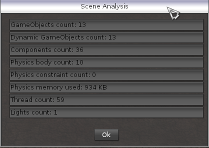
- Scene Analysis: Performs a scene analysis and shows the results in a dialog. That is, how many game objects, components, physics objects, constraints, physics memory, thread etc. are used.
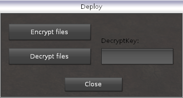
- Deploy: Deploys the project, so that it can be used for installation on a different computer. A dialog is shown, in which the designer may decide whether to crypt all lscene and ua files, so that other users may not change the logic. The result is a setup file, created with the inno tool.
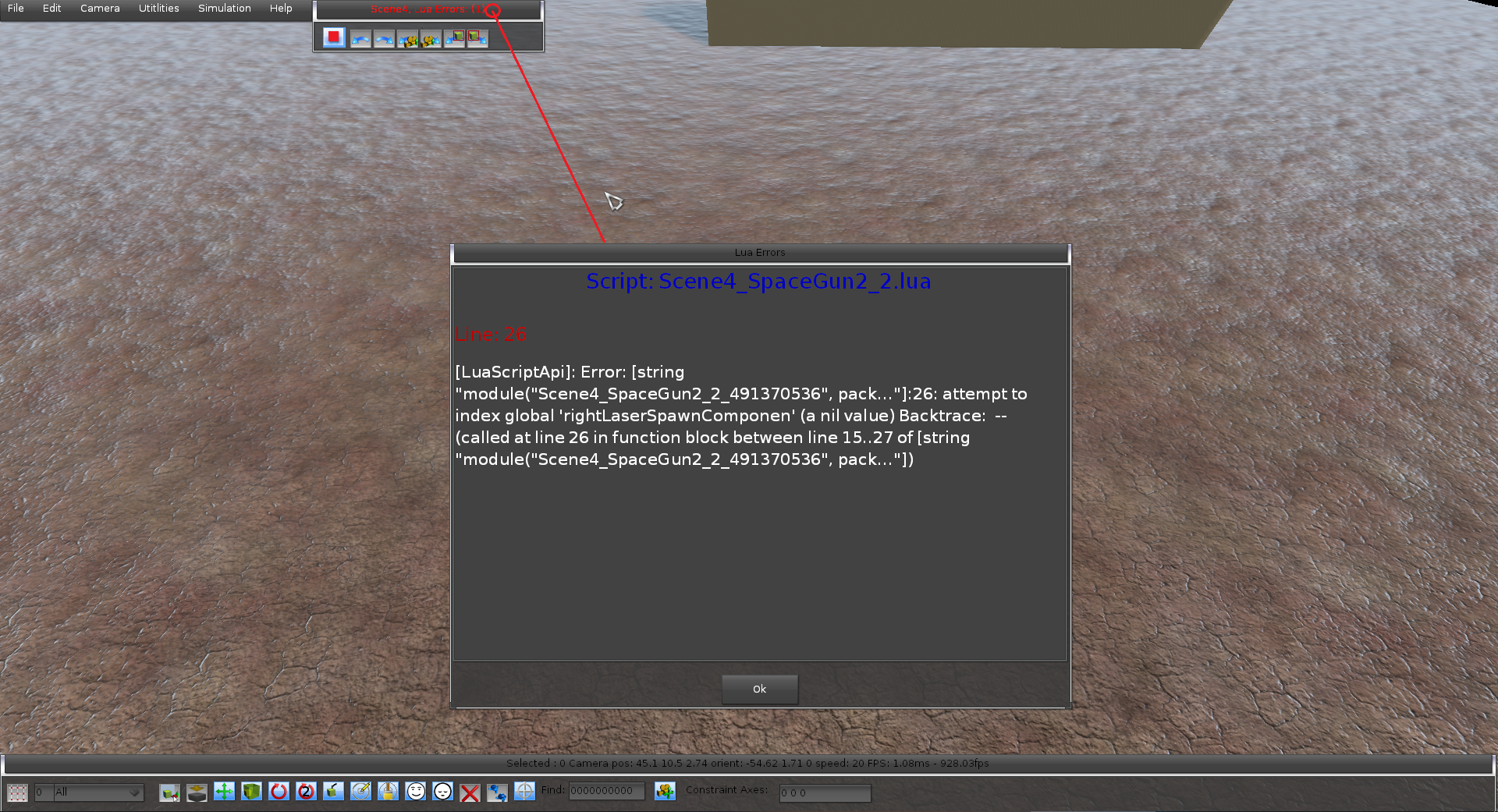
- Lua Errors: When starting the scene and some lua runtime errors occur, the errors will be shown in the middle of the screen. (Bild hinzufügen). When the user clicks on the title bar, the Lua Errors dialog will be opened with further information, in which line the error occured etc. This dialog can also be opened via this menu entry.
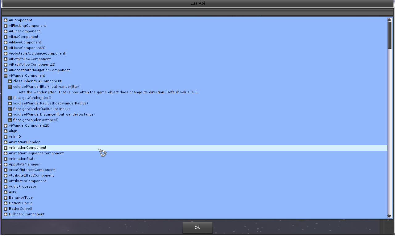
- Lua Api: All yet available lua functions and classes are presented in this dialog as dictionary. Its also possible to search for functions etc. For each function there is also a descriptions, some hints etc.
- Draw Navigation Mesh: If Recast navigation is used, using this menu entry, the navigation mesh will be extended by some debug lines in different colors with walkable passages.
- Optimize Scene: Goes through all game objects and checks, if a game object has a physics artifact component or a kind of physics active component and sets the ‚Dynamic‘ attribute of the game object properly.
Simulation
- Control Selected Player: If the PlayerControllerComponent is used, selecting a player or an other target, the simulation starts and the target can be controlled by a specifed device (keyboard, controller, mouse).
- Test Selected Gameobjects: During the design process a scene may be become really complex and if the designer wants just to test some game objects and its logic (phyics, AI etc.), its not desired, that life is breathed to all game objects. Thus its possible to just selected the desired game objects and use this function, in order to just test this game objects logic. Internally, all other game objects will be de-activated and its internal activation state restored, when the simulation does stop.
Help
- About: Shows some information about the NOWA-Engine and NOWA-Design, like which 3rd party libraries are used etc. and its license.
Middle panel for actions
- Play/Stop: Starts the simulation. When the simulation is stopped, all game objects will reclaim their old transform values and also changed attributes are reset. But attention: If lua scripts are used, in which states of game objects are changed. The designer/developer must unsure, that those attributes are reset manually, when the function ‚disconnect‘ is called. Because due to performance and memory reasons, its not possible for NOWA-Design, to track those runtime script states.
- Undo/Redo: See menu entries.
- Selection Undo/Redo: See menu entries.
- Camera Undo/Redo: See menu entries.
Note: If the ‚Escape‘-key is pressed, when starting the simulation and ending it, all game objects will remain at its new current position! This can be useful, if the designer wants to create some chaos in the scene. E.g. placing some rocks on the air and let them fall down into the world, taking care of the physics, where the stones will land.
Lets start with creating a new scene.
Bild mit Einstellungsmöglichkeiten und diese beschreiben. Auch private key
Click on File -> New, a panel appears in which a lot can be configured. Lets describe the sections and its configuration parameter.
Project section
The project section has the following configuration parameters:
- Project Name: The project name to set. When typing the name, a check is automatically made, if the given project name does already exist and the correponding feedback is shown.
- Scene Name: The scene name within the project name. Also while typing, all yet created scene names are listed for better orientation.
- Crypt Key: A private key number, which can be specified to protect the scene’s and lua content of a project for unallowed modifications (cheating etc.). When a project is deployed (see Utilities -> Deploy). All scenes and lua files will be crypted with that key if desired and can also be decrypted with your key. Hence its important for project to remember the key number! Else your files are lost and can no more be decrypted! Note: If a new project with the first scene is created and the key set, when creating new other projects or scenes, always this key is used! The key is stored for all projects and scenes! When the key is changed one time, its changed also for all projects and scenes.
- Create C++ Project: If acitvated, a new C++ project is also created in visual studio, with project name and the scene is also loaded automatically. This acts as starting point, for creating a game. Lots of content is pre-configured already in order to ease the development.
- Open Project: If activated, the created or existing C++ project will also be opened directly.
- Create Scene In Own State: A project usually is composed of several scenes, like intro, menu, options, save, load etc. If activating this property, for the existing project a new AppState with the scene name is created. The AppState is like its own solar system. It has its own scene manager, physics, audio etc. The state can be stacked onto another state. Image a running game, in which the player presses the escape key. The game state will be paused and the menu state pushed on the top of the game state, because the player wants to lower the background music volume. After that, he wants to resume the game. Or another example is saving a game, or loading a different game. Such own AppStates should only be used for such scenarios. If your game is composed e.g. of several levels, there is no necessity to create for each level an own state, as this would blow the whole application, as each state has its own infrastructure and occupies a lot of memory. When having a lot of scenes, they may be used just in the GameState and the GameProgressModule can be adapted, to just load a different scene in the same GameState if a goal e.g. is reached.
- Ignore Global Scene: Its a more advanced setting. Remember as told above, when creating a project, always a global.scene file is created, which may contain all global game objects. That means, when loading a different scene, the global game objects are also available for that scene. This is not desired for each scene! Imagine a game menu with graphics options. In this scene its not desired, that a global player game object is loaded each time. Thus if setting this property to true, this scene will not load any global game objects.
SceneManager section
The scene manager section desribes all global graphics options for the Ogre scene manager.
- Ambient Light Upper Hemisphere: Ambient color when the surface normal is close to hemisphere direction. Tip: Set the upperHemisphere to a cold color (e.g. blueish sky) and lowerHemisphere to a warm color (e.g. sun-yellowish, orange) and the hemisphere direction in the opposite direction of your main directional light for a convincing look.
- Ambient Light Lower Hemisphere: Ambient colour when the surface normal is pointing away from hemisphere direction.
- Opposite Directional Light: Sets whether the hemisphere should point to the same direction as the directional light, or the opposite.
- Shadow Far Distance: Sets the default maximum distance away from the camera that shadows will be visible. Shadow techniques can be expensive, therefore it is a good idea to limit them to being rendered close to the camera if possible, and to skip the expense of rendering shadows for distance objects. This method allows you to set the distance at which shadows will no longer be rendered.
- Shadow Directional Light Extrusion Distance: Sets the distance a shadow volume is extruded for a directional light. Although directional lights are essentially infinite, there are many reasons to limit the shadow extrusion distance to a finite number, not least of which is compatibility with older cards (which do not support infinite positions), and shadow caster elimination. The default value is 10,000 meters. This does not apply to point lights or spotlights, since they extrude up to their attenuation range.
- Shadow Directional Light Texture Offset: Sets the proportional distance which a texture shadow which is generated from a directional light will be offset into the camera view to make best use of texture space. When generating a shadow texture from a directional light, an approximation is used since it is not possible to render the entire scene to one texture. The texture is projected onto an area centred on the camera, and is the shadow far distance
- 2 in length (it is square). This wastes a lot of texture space outside the frustum though, so this offset allows you to move the texture in front of the camera more. However, be aware that this can cause a little shadow ‚jittering‘ during rotation, and that if you move it too far then you’ll start to get artefacts close to the camera. The value is represented as a proportion of the shadow far distance, and the default is 0.6.
- Shadow Color: Set the colour used to modulate areas in shadow
- Shadow Quality: Several shadow quality levels. The higher the level, the better the shadow quality, but the more the performance impact. Possible values:
- PCF 2×2: Standard quality, very fast
- PCF 3×3: Good quality. Still quite fast on most modern hardware.
- PCF 4×4: High quality. Very slow in old hardware (i.e. DX10 level hw and below).
- PCF 5×5: Better and slower than 4×4, same considerations.
- PCF 6×6: Better and slower than 5×5, same considerations.
- Exponential Shadow Maps: High quality. Produces soft shadows. It’s much more expensive but given its blurry results, you can reduce resolution and/or use less PSSM splits which gives you very competing performance with great results.
- Ambient Light Mode: Sets the ambient light mode. Possible values are:
- Ambient Auto: Use fixed-colour ambient lighting when upper hemisphere = lower hemisphere, use hemisphere lighting when they don’t match. Disables ambient lighting if the colours are black.
- Ambient Fixed: Force fixed-colour ambient light. Only uses the upper hemisphere paramter.
- Ambient Hemisphere: Force hemisphere ambient light. Useful if you plan on adjusting the colours dynamically very often and this might cause swapping shaders.
- Ambient Spherical Harmonics: Uses spherical harmonics
- Ambient Spherical Harmonics Monochrome: Uses spherical harmonics (monochrome / single channel)
- Ambient None: Disable ambient lighting.
- Forward Mode: Forward3D and Clustered are techniques capable of rendering many lights. It is required in order to render non-shadow casting non-directional lights with the PBS implementation. Deferred shading has a lot of problems (transparency, antialiasing, multiple BDRF). Besides, it uses a lot of bandwidth. Forward+/Forward2.5 is great, but requires DX11 HW (needs UAV) and a Z-Prepass. It’s not superior on all accounts, but it can work on DX10 hardware and doesn’t require a Z-prepass. The result is a nice generic algorithm that can run on a lot of hardware and can handle a lot of lights. Whether it performs better or worse than Deferred or Forward+ depends on the scene. Like its alternatives Defered and Forward+, it works best with many small lights, or few big lights. Forward3D and Clustered have many parameters. Setting the parameters is a trade quality for speed; but sometimes some presets work better on some scenarios than others. Tip: It may be better to have fewer but bigger lights in outdoor scenes. Also avoid keeping too many lights tight in the same place. The Light’s size has a direct impact on quality. Theoretically all lights have an unlimited range. However we cut it off after certain threshold for performance reasons. Very low thresholds stress the F3D system, but very high thresholds will cut the light too early.
- Light Width: The width of the view-space grid. Recommended value is 4 unless number of slices is very small.
- Light Height: The height of the view-space grid. Recommended value is 4 unless number of slices is very small.
- Number Of Light Slices: The number of slices. Each additional slice consumes much more memory. The width and height is doubled on each slice. It’s like mipmapping but on reverse.
- Lights Per Cell: The maximum number of lights a cell in the grid can hold.
- Decals Per Cell: Maximum number of decals a cell in the grid can hold. 0 to disable decals.
- Min Light Distance: Bias towards the camera for grid.
- Max Light Distance: How far the grid array can go.
Physics section
The physics section describes all global physics parameter for newton dynamic physics.
- Physics Update Rate: Usually 120 frames per second (twice of graphics, if vsync is set to on). In this case the physics will run fluently but requires more performance. Maybe 60 FPS do also suffice.
- Solver Model: Setting the solver model allows sacrificing accuracy and realism for speed, good for games, etc. for a more detailed description of how to use this function, see the Newton documentation.
- Solver For Single Island: Enables or disables multithreading for single collision islands. Newton groups collision primitives into so called collision islands to increase the efficiency of the broadphase collision detection. These collision islands represent disjunct sets of possibly colliding objects. By default multithreading is not enabled for single collision islands but only for separate islands. Using this function one can alter this default behavior of Newton.
- 1 – Significant software cost to set up threads, as well as instruction overhead.
- 2 – Different systems have different cost for running separate threads in a shared memory environment.
- 3 – Parallel algorithms often have decreased converge rate. This can be as high as half of the of the sequential version. Consequently, the parallel solver requires a higher number of interactions to achieve similar convergence.
- Note: It is recommended this option is enabled on system with more than two cores, since the performance gain in a dual core system are marginally better. Your mileage may vary. At the very least the application must test the option to verify the performance gains.
- Broad Phase Algorithm: Sets the broad phase algorithm. This parameter does not need to be modified.
- Physics Thread Count: The threads count, which newton can use for parallelism. This parameter does not need to be modified.
- Linear Damping: The global linear damping for all game objects, that are using a kind of physics component.
- Angular Damping: The global angular damping for all game objects, that are using a kind of physics component.
- Gravity: The global gravity for all game objects, that are using a kind of physics component.
Multi threaded mode is not always faster. Among the reasons are
Recast Navigation section
The recast navigation section describes all parameters, if A
- Use Recast: Whether A
- path navigation is used in the scene.
- Cell Size: Is the width and depth resolution used when sampling the source geometry. The width and depth of the cell columns that make up voxel fields. Cells are laid out on the width/depth plane of voxel fields. Width is associated with the x-axis of the source geometry. Depth is associated with the z-axis. A lower value allows for the generated meshes to more closely match the source geometry, but at a higher processing and memory cost. The xz-plane cell size to use for fields. [Limit: > 0] [Units: wu]. CellSize and CellHeight define voxel/grid/cell size. So their values have significant side effects on all parameters defined in voxel units. The minimum value for this parameter depends on the platform’s floating point accuracy, with the practical minimum usually around 0.05.
- Cell Height: Is the height resolution used when sampling the source geometry. The height of the voxels in voxel fields. Height is associated with the y-axis of the source geometry. A smaller value allows for the final meshes to more closely match the source geometry at a potentially higher processing cost. (Unlike cellSize, using a lower value for cellHeight does not significantly increase memory use.) The y-axis cell size to use for fields. [Limit: > 0] [Units: wu]. CellSize and CellHeight define voxel/grid/cell size. So their values have significant side effects on all parameters defined in voxel units. The minimum value for this parameter depends on the platform’s floating point accuracy, with the practical minimum usually around 0.05. Setting ch lower will result in more accurate detection of areas the agent can still pass under, as min walkable height is discretisized in number of cells. Also walkableClimb’s precision is affected by ch in the same way, along with some other parameters.
- Agent Max Slope: The maximum slope that is considered traversable (in degrees). [Limits: 0 <= value < 90]. The practical upper limit for this parameter is usually around 85 degrees.
- Agent Max Climb: The Maximum ledge height that is considered to still be traversable. This parameter serves at setting walkableClimb (maxTraversableStep) parameter, precision of this parameter is determined by cell height (ch). [Limit: >=0]. Allows the mesh to flow over low lying obstructions such as curbs and up/down stairways. The value is usually set to how far up/down an agent can step.
- Agent Height: The height of an agent. Defines the minimum height that agents can walk under. Parts of the navmesh with lower ceilings will be pruned off. This parameter serves at setting walkableHeight (minTraversableHeight) parameter, precision of this parameter is determined by cell height.
- Agent Radius: The radius on the xz (ground) plane of the circle that describes the agent (character) size. Serves at setting walkableRadius (traversableAreaBorderSize) parameter, the precision of walkableRadius is affected by cellSize (cs). This parameter is also used by DetourCrowd to determine the area other agents have to avoid in order not to collide with an agent. The distance to erode/shrink the walkable area of the height field away from obstructions. [Limit: >=0]. In general, this is the closest any part of the final mesh should get to an obstruction in the source geometry. It is usually set to the maximum agent radius. While a value of zero is legal, it is not recommended and can result in odd edge case issues. The agent would be to fat to pass that area :).
- Edge Max Len: The maximum allowed length for contour edges along the border of the mesh. [Limit: >=0]. Extra vertices will be inserted as needed to keep contour edges below this length. A value of zero effectively disables this feature. Serves at setting maxEdgeLen, the precision of maxEdgeLen is affected by cell size.
- Edge Max Error: The maximum distance a simplified contour’s border edges should deviate the original raw contour. (edge matching). [Limit: >=0] [Units: wu]. The effect of this parameter only applies to the xz-plane. Also called maxSimplificationError or edgeMaxDeviation. The maximum distance the edges of meshes may deviate from the source geometry. A lower value will result in mesh edges following the xz-plane geometry contour more accurately at the expense of an increased triangle count. A value to zero is not recommended since it can result in a large increase in the number of polygons in the final meshes at a high processing cost.
- Region Min Size: The minimum number of cells allowed to form isolated island areas (size). [Limit: >=0]. Any regions that are smaller than this area will be marked as unwalkable. This is useful in removing useless regions that can sometimes form on geometry such as table tops, box tops, etc. Serves at setting minRegionArea, which will be set to the square of this value (the regions are square, thus area = size
- size).
- Region Merge Size: Any regions with a span count smaller than this value will, if possible, be merged with larger regions. [Limit: >=0] [Units: vx]. Serves at setting MergeRegionArea, which will be set to the square of this value (the regions are square, thus area = size
- size).
- Vertices Per Polygon: The maximum number of vertices allowed for polygons generated during the contour to polygon conversion process. [Limit: >= 3]. If the mesh data is to be used to construct a Detour navigation mesh, then the upper limit is limited to <= DT_VERTS_PER_POLYGON (=6). The maximum number of vertices per polygon for polygons generated during the voxel to polygon conversion process. Higher values increase processing cost, but can also result in better formed polygons in the final meshes. A value of around 6 is generally adequate with diminishing returns for higher values.
Detail Sample Distance: Sets the sampling distance to use when generating the detail mesh. (For height detail only.) [Limits: 0 or >= 0.9] [Units: wu]. Also called contourSampleDistance. Sets the sampling distance to use when matching the detail mesh to the surface of the original geometry. Impacts how well the final detail mesh conforms to the surface contour of the original geometry. Higher values result in a detail mesh which conforms more closely to the original geometry’s surface at the cost of a higher final triangle count and higher processing cost. Setting this argument to less than 0.9 disables this functionality.
sdf
Toolbar
The widgets in the tool bar are used for direct manipulation in the editor.
- Grid Button: Shows a grid, in order to help position game objects more precisely. Also all game objects are snapped on that grid. Also when in place mode and holding the shift button, will place the game object in grid mode.
- Grid Value: Sets the grid value in meters.
- Categories: Sets the category or categories of game objects. Only game objects, that are part of the category can be selected. E.g. if the designer wants to select just all enemies. He sets that category filter and presses ctrl + a. Categories can also be combined like ‚Player+Enemy‘, or ‚All-Player‘, if every game objects besides the player should be selectable.
- Select Mode: Activates the game object select mode. Note: Also a selection rectangle can be used to select several game objects, or using control, individual game objects can be selected and de-selected.
- Place Mode: Activates the place mode, so that resources can be placed into the scene. Using the mouse wheel will rotate the game object in the corresponding direction by 45 degrees. There are also 3 modes:
- Normal: Just usual placement at y zero position.
- Stack: Stacks the game object above another already placed game objects.
- Stack Orientated: Stacks the game object above another already placed game objects and also orientates along the normal plane of the already placed game object below.
- Translate Mode: Shows the translation gizmo, in order to translate one or several game objects.
- Scale Mode: Shows the scale gizmo, in order to scale one or several game objects.
- Rotation 1 Mode: Shows the rotation gizmo, in order to rotate one or several game objects around its local center.
- Rotation 2 Mode: Shows the rotation gizmo, in order to rotate one or several game objects around the center of all selected game objects.
- Pick Mode: Starts the simulation and activates the picking mode, so that physically active game objects can be pulled by a rope for physics testing purposes.
- Modify Terrain Mode: If a terra component is used, the terrain can be modified in this mode.
- Paint Terrain Mode: If a terra component is used, the terrain can be painted in this mode.
- Wake Button: Wakes all physically active game objects.
- Sleep Button: Sets all physically active game objects to sleep mode, so that they will not move automatically.
- Remove Button: Removes one or several selected game objects.
- Copy Button: Copies one or several selected game objects and after that passes over to translation mode, showing the translation gizmo.
- Focus Button: Setting a game object id in the text box, the camera will focus the given game object.
- Camera Reset Button: Resets the camera to origin of the scene.
- Constraint Axis Textbox: One axis can be constraint, so that its only possible to translate the game objects along 2 axes. Note: This is usefull if creating e.g. a 2,5D plattformer game. When setting the constraint axis to 0 0 1. The z-axis is gone, so that its only possible to place and move game objects along the x-y axis.
Note:The camera speed can be increased/decreased by holding the shift button and using the scroll wheel.
NOWA-Design Overview
The picture below, shows the NOWA-Design overview.
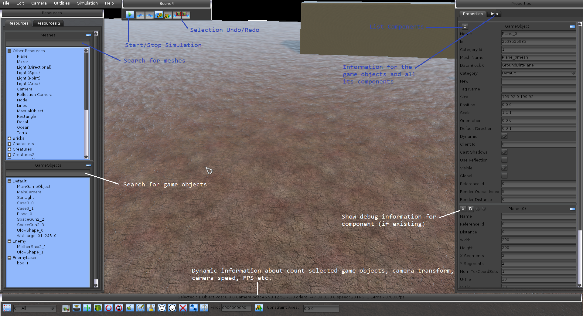
Left Panels
On the left side of the editor, the resources panel is shown, which shows a tree of resources, that can be placed. Also some special game objects can be created like terra, plane, light etc.
Below the resources panel, the used game objects in the scene are shown grouped by their category. The game objects can also be selected or deleted via this tree.
On the other tab, all known datablock names are shown. A material name e.g. can be copied and set for a game objects’s entity, to change the datablock.
There is also a tab with all known images. Note: All resources can also be searched with an auto complete functionality. Its even possible to e.g. just type ’ster‘ and ‚monster‘ would match.
Right Panels
On the right side of the editor, the attributes panel is shown for one or several selected game objects. In this panel, also all components are shown and on the other tab also some details for each component.
Note: If several game objects are selected, only the same attributes and values are shown and a manipulation can be done for all the selected game objects. All other attributes just show ’several values‘ hint.
A new component can be either added by clicking the ‚C‘-button or ctrl+shift+c. In this case a list of components is shown and if the cursors is set above a component, some information is printed as tool tip.
Note: Only components are enabled, which are valid to add considering the constraints of the game object. E.g. it does not make sense, to add a joint component, if the game object has no phyics component.
Components can also be re-ordered, for better reading, since the amount of attributes may grow.
Each component contains also a ‚d‘-button, which stand for debug. Some components like joints show some debug information, if simulation is active for better analysis, what is going on. Or the time line components, activates more detailed log in order to show, when which time point has been reached. Each component can also have a name. This is useful, if there are several similiar components like MyGUI widgets components, that are used in lua scripts for better code readability.
Note: In each scene, there are already 3 game objects present, which cannot be deleted.
- MainGameObject: The main game object has the id ‚1111111111‘ and is present in each scene. Its can be used for things like setting MyGUI widget components, or physics material components etc. and is easy to find. Its like in C++ the main function.
- MainCamera: The main camera has the id ‚1111111112‘ and is the ‚eye‘ of the scene. When creating a new scene, the camera has also automatically a default workspace component created, which takes care of the rendering of the scene. This can be changed to another kind of workspace, like one with HDR effects, or reflection or background, or sky etc. Note: Its also possible to place further cameras in the scene and switch between them (even via lua). Each camera has its own workspace component. But at a time, only one camera is always the main eye.
- SunLight: The game object with the sun light has the id ‚1111111113‘. Its the main light, which lightens the scene and the light parameter in the main menu of the scene manager are using this light for ambient lightning.
Game Object Attributes
The game object is composed of a list of attributes for direct manipulation.
- Id: The id of the game object. Its unique in the whole scene. It can be used for identification and as reference of other components.
- Name: The name of the game object. Note: If the name already does exist, an incremented number ‚_count‘ will be added to the game object automatically.
- Category Id: Readonly category id number.
- Category Name: A text field, in which a new category name can be specified. Categories are used for ray cast and filtering game objects. Also the physics system is using the categories.
- Mesh Name: The read only mesh name, that is used for the game object’s visual represenstation.
- Tag Name: A tag name is like a sub-category. The background is, that its only possible to create 31 different categories, due to performance reasons. So its a good idea to subdevide a category to different tags. For example a category could be ‚Enemy‘ and the tags for each game object could be ‚Ship1‘, ‚Boss1‘, ‚Boss2‘ etc.
- Datablock: The datablock which is used for physically based rendering (roughness, normal map, diffuse etc.). A different dtablock can also be set for rendering. When the DataBlockPbsComponent is added, the current datablock also can be manipulated more fine granularily.
- Use Reflection: In a workspace, that uses reflection, this switch for the game object can be activated, so that it will be reflected in the scene.
- Controlled By Client Id: In a network scenario, an id can be set, which specifies, which client does control this game object.
- Cast Shadows: If activated, this game object does cast shadows.
- Visible: Sets whether this game object is visible (rendered) or not
- Dynamic: Sets whether this game object is dynamic and is moved frequently in the scene. Note: Set this attribute to false, if you are sure, this game object will be never moved later. Ogre does then a good job increasing performance of the whole scene. Assets in the scene like trees, grass, buildings etc. can be static. Another indicator would be, if this game object uses a PhysicsArtifactComponent. In this case, dynamic can be deactivated. If the game object e.g. uses a kind of physics active component. This attribute should be activated. If you are finished, you can use in the menu the Utilities -> Optimize Scene dialog, which will also set this attribute properly.
- Size: Readonly attribute, which shows the size of the mesh in meters.
- Position: The current position of the game object.
- Scale: The current scale of the game object.
- Orientation: The current orientation of the game object.
- Default Direction: The default direction in local space of the mesh. That is, in which direction this mesh has been created my a 3D model application. This is necessary e.g. for all ai-components, if this game object is used as agent, in order to determine the front facing.
- Global: Sets whether this game object is a global one. It will be then stored to the global.scene instead to each scene. Its like a static object for all scenes. See also description in the new scene panel.
- Clamp Y: Sets whether this game object will be clamped at y on the top of another game object if loaded. This can be necessary in conjunction with the attribute ‚Global‘. For example, if the player game object is global and loaded in different scenes, the floor may be at an different height, so it may be necessary to clamp y of the player, so that he will stand on the ground and not in air and fall down.
- Reference Id: The reference id to another game object or component can be set, for cascading activation of components. E.g. if the player pulls a lever, setting the reference id to a door, which also has a sound etc. the door joint will be activated and the sound also activated and played.
- Render Queue Index: The render queue index, which specifies the rendering order. Game objects with a higher render index will be rendered after game objects with a lower render index (z-ordering).
- Render Distance: The render distance until which the game object is rendered in meters, 0 means infinite.